Tuesday 30 October 2012

Work Flow

To have a smooth process when creating my models, I will predict and look into my work flow and programmes used.
This is so any problems I think I will come across will hopefully be solved now rather than later, and therefore my project in Ba8 will run as smoothly as possible. If I come across serious problems and don't know how to get past them I will then easier have time to contact someone for help.

So to start with I found this very helpful tutorial which spans over several Youtube videos.

1. UndergroundEducation (2010) Maya to ZBrush to UDK - Part 1 - Setting up [YouTube video] Available at <http://www.youtube.com/watch?v=2ky-ooDV8U4&feature=relmfu> Accessed 30th October 2012

He starts off by setting up his scene, which I haven't done as I don't want to make Maya too personal for good practise when in the industry. But I have watched it and understand how to acomplish these if I ever need.

2. UndergroundEducation (2010) Maya to ZBrush to UDK - Part 2 - Modelling in Maya [YouTube video] Available at <http://www.youtube.com/watch?v=_xIGPTHegyI&feature=relmfu> Accessed 30th October 2012

Following this tutorial I have used a sphere to save time and to look at a messy UV (as he isn't looking into it) and therefore I can learn how to clean up UV's for my future models.

So I started off creating a sphere:


I then added a texture, which I later realised was pointless because the texture I'll be adding will be My ZBrush texture so will have to cover this one up anyway, but I'll change it when I get to that.
But I did check out my UV's which did  seem fine and don't need much changing however I looked at how he was snapping some points that on the model are together but on the UVs aren't so I too snapped my own. (All of the triangle points form one point.)


3. UndergroundEducation (2010) Maya to ZBrush to UDK - Part 3 - Modelling in Maya Continued. [YouTube video] Available at <http://www.youtube.com/watch?v=Z1TBAJ0R0xM&feature=relmfu> Accessed 30th October 2012

This Video was about creating and adding to the model, of course I would be doing this if I was creating my objects later, however for this try out I decided not to as I feel my sphere is good enough for what I need to do.

4. UndergroundEducation (2010) Maya to ZBrush to UDK - Part 4 - Modelling in Maya Continued. [YouTube video] Available at <http://www.youtube.com/watch?v=WviYebNJhtw&feature=relmfu> Accessed 30th October 2012

Following this guys advice, I have deleted my history and moved my pivot point (by pressing 'D' and 'V' to snap) to the bottom of my sphere for better accuracy when placing it in a scene in UDK. And then snapping it back to the centre of my scene.


He also goes on to talk about measurements that would fit the UDK environment, which I didn't think about. So I went to check some measurements so they would help me with my models.

256 UU = 487.68 cm = 16 feet.
1 meter = 52.5 UU
1 foot = 16 UU
1 cm = 0.525 UU
1 UU = 0.75 inches

(Unreal Unit)

Bleah. UDK Player Scale Polycount [Forum] Available at <http://www.polycount.com/forum/archive/index.php/t-74537.html> Accessed 30th October 2012
Unreal Unit Wiki Available at <http://wiki.beyondunreal.com/UU> Accessed 30th October 2012

My child is, so I have to consider what my assets and objects in this room will be sized in comparison to her. (Create> Measurement Tools> Distance Tools) For this my ball is a football size being 22.5cm which would equal 11.8 UU. (Henbrandt) And because one Maya Unit to Unreal Units I have to make sure my sphere is 11.8 MU.


Henbrandt (2012) Uninflated Plastic Football 22.5cm, colour varies, one supplied Amazon Available at <http://www.amazon.co.uk/Uninflated-Plastic-Football-22-5cm-supplied/dp/B0026RRNGE/ref=acc_glance_sg_ai_ps_t_3> Accessed 30th October 2012

5. UndergroundEducation (2010) Maya to ZBrush to UDK - Part 5 - Modelling in Maya Continued. [YouTube video] Available at <http://www.youtube.com/watch?v=T5pVPf6p3h8&feature=relmfu> Accessed 30th October 2012

Now I need to check my translations by freezing them, and deleting my history. Then make and set my new project to make sure, for future reference, I have the correct folders for important things. Finally before exporting as an object I need to check I can export as an .obj file in the plug-in manager.(Window> Settings/Preferences>Plug-in Manager)

Now I can export using the Export selected, clicking on the box to adjust settings. Making sure it's an obj export and not maya binary. I have also left all of my settings on, as my sphere is quite simple and wont be effected by exporting things that aren't there. This means I can keep them on for future, more complicated, exports.
And now I have exported my .obj file (plus in the correct file)
 
6. UndergroundEducation (2010) Maya to ZBrush to UDK - Part 6 - Importing to ZBrush. [YouTube video] Available at <http://www.youtube.com/watch?v=_C7n2CDhMo8&feature=endscreen> Accessed 6th November 2012

Importing the file through the tools box and then dragging it on the scene will make the sphere show up. I can then play around with perspective 'P' to make the object have an isometric view or a perspective one.


He also mentions to save a 'Morph Target' I don't quite understand this, but he says it will be important later and is probably one of the first things I should do when opening a new ZBrush tool.
For corners and flat edges that are wanting to kept so, he says to make sure I crease the object so that when I subdivide the corners don't round off.
To hide certain areas, turn on draw PolyFrame to see better and then select the interior faces, of the flat surface. Do this twice to select all necessary faces. Ctrl+shift+click will invert this. And I can then 'group visible' at different poly areas I want to visually separate.

7. UndergroundEducation (2010) Maya to ZBrush to UDK - Part 7 - Creases and subdividing in ZBrush. [YouTube video] Available at <http://www.youtube.com/watch?v=7COJgcSVjPw&feature=relmfu>

I would then select every visible face and crease each one.
These changes I've made will be a normal/bump map and the displacements will be a height map.
I have also divided my mesh a couple of times.

8. UndergroundEducation (2010) Maya to ZBrush to UDK - Part 8 - Smoothing the Mesh in ZBrush. [YouTube video] Available at <http://www.youtube.com/watch?v=F16PHVH_0YM&feature=endscreenv=F16PHVH_0YM&feature=endscreen>


I managed to mask off a certain area so I was able to sculpt the other parts.

9. UndergroundEducation (2010) Maya to ZBrush to UDK - Part 9 - Saving and Layers in ZBrush. [YouTube video] Available at <http://www.youtube.com/watch?v=fjOGgIzqZKc&feature=relmfu>

So using my masked areas, I can now go into deformation and adjust this non selected area in a very precise way.
So far I have just moved the size

11. UndergroundEducation (2010) Maya to ZBrush to UDK - Part 11 - Blocking out the Rest of Basic Detail. [YouTube video] Available at <http://www.youtube.com/watch?v=ufLC6TqWPEc&feature=relmfu> Accessed 9th November 2012

Ctrl and Alt is a minus mask tool, so I can take away a mask when I've done a mistake.

From here on he is basically sculpting which I have followed and understood but didn't think much of what I have learnt can be rephrased here and make it sound interesting. So I've skipped onto the next important video and here is my basic textured sphere:


Making sure the colour has been filled, and using RGB selected and Z add and Z sub not. We can add colour to this sphere.


23. UndergroundEducation (2010) Maya to ZBrush to UDK - Part 23 - Exporting the Normal and Displacement Maps. [YouTube video] Available at <http://www.youtube.com/watch?v=rHJ9RWoQhLI&feature=relmfu> Accessed 12th November 2012

Now we are going to get a Displacement and Normal map, and you start off by turning on adaptive scan mode which decides which areas need more or less detail in. (image res set to 1024)

Normal map needs to be clicked on tangent and setting the subdivision level to the lowest.
IF - you wanted to attach these to the original mesh in Maya then this is the time that you would have to got to the morph target tab and 'switch' to it. The displacement map can then be created and consequently found in the alpha drop down menu, and often need to be flipped.
The normal map can then be created. These can be saved as Photoshop files, so they can then be adjusted in Photoshop if needed.

The morph target doesn't have to be used if i am not in a pipeline with a set mesh. So I can in fact export my new obj file.

This also helped: http://www.youtube.com/watch?v=xaGMq1YJwio
And qRemesher tool can be used to re-topologise. : http://www.youtube.com/watch?v=nEriFHOD4VA

25. UndergroundEducation (2010) Maya to ZBrush to UDK - Part 25 - Bringing in the mesh and setting up the material. [YouTube video] Available at <http://www.youtube.com/watch?v=Q7MJTYLePF8&feature=relmfu> Accessed 16th November 2012

The first thing that is done here if to import the model from Maya into UDK using the axmesh, which needs the installed actor X, which I haven't got. But after looking into it, I realised another way of exporting the model as FBX. I can't seem to export my object in Zbrush as FBX so will have to do this through Maya.

THIS ALL WENT WRONG
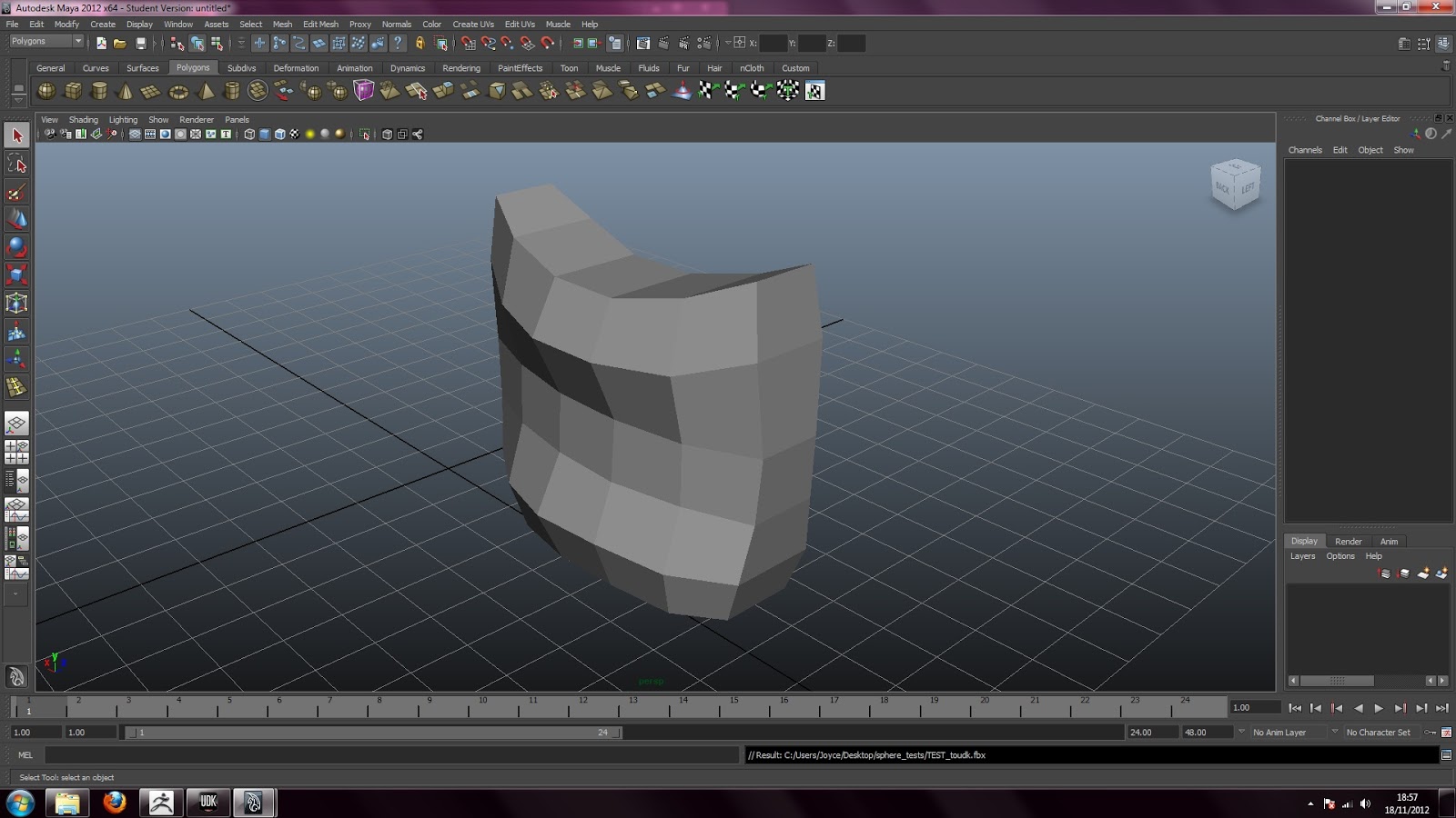
It took a while, but I understand what went wrong. The triangle polys in Maya on my sphere weren't being handled well in ZBrush, I had forgetting and figured it would be ok. But clearly not at the UV's would be messed up and so would all my maps. So i new 'squarer' object has been made.
I have sculpted, coloured, and exported all maps as shown before for this new simple model. and found this does work lots better.


And this is my Maya file thats been in ZBrush and I've imported back the lowest res model into here so that I can save it as an FBX file, compatible with UDK.

I later had a problem with plug in smoothing and found help here: http://download.autodesk.com/us/fbx/20112/Maya/_index.html

This video also shows how to add materials and textures to the static mesh. and I have finally worked out how to do it, One reason being I forgot to flip the maps vertically.


You have to import them all, and use the colour map as a new material and go into that sub menu to assign it to the object chosen. Placing the RGB selector to the diffuse, it shows up on the left.

After this, i assign the new material and this drag it on screen and there we have it, my odd models in UDK.


The next thing was to create collisions, which I did with the help of a couple of tutorials: http://www.youtube.com/watch?v=Iv5NO1Z8JXE
http://www.3dmotive.com/training/free/creating-mesh-collision-for-udk/?follow=true
and 
28. UndergroundEducation (2010) Maya to ZBrush to UDK - Part 28 - Testing the material in game and creating collision meshes. [YouTube video] Available at <http://www.youtube.com/watch?v=u4a2h7T0E8U&feature=relmfu> Accessed 18th November 2012


And I managed to create a simple box collision which I am happy with for this tutorial.

Steven Hird an artist in the industry has helped me create a simple Mental ray render from his step by steps:

Intro

1

2

3

4

5

6


  • First off in the first image you'll see in the plug in's menu you need to select
Window - Settings/Preferences - Plug in Manager , make sure Mayatommr.mll is ticked and also , Auto load across from it. 
 

  •  MR screen 01 select the fourth camera option to bring up the render menu and from here select in the drop down . mental ray
  •  MR Screen 02 scroll down and select the camera you want to render from, then select the aspect ratio, here's it's shown at just 640 x 480
  •  MR Screen 03 in the same menu, select quality and then select Max sample and set it to 2, this will reduce any rough edges in your render, the higher the setting the smoother.
  • MR Screen04 same menu, select Features, tick Final Gathering
  • MR Screen05 same menu, select Indirect Lighting, at the side of Physical Sun and Sky, select 'Create'
  • MR screen 06 select the second camera along to render your scene from the camera you selected and you'll see the same result as shown in my pic.

This has helped me create a simple render of my test of sun lighting:


I also managed to create a scene with spot lights roughly using this tutorial: http://www.youtube.com/watch?v=sqrj9o4uM6g


 This is how I am going to create a scene with lighting, if needed, in UDK: http://www.worldofleveldesign.com/categories/udk/udk-how-add-lights-dominant-directional-light-point-light.php

And finally ZBrush lighting can be done like this: http://www.pixologic.com/zclassroom/homeroom/lesson/lighting/

Monday 29 October 2012

My Girl

To establish what sort of Dressing Table and objects I will be creating, I want to flesh out a little of the character that will be living in it.

Inspired by the magazine for children along the same age I was aiming for, I want my 10 year old girl to be the pinkest prettier princess ever.


The type of girl who will live in the scene I will create is a 10 year old girl who loves princess things (hence a dressing table). She is a sweet child, but her personals make her seem spoilt having everything girly she wants. The standard pink, purple, yellow, green pastel colours attract her which are the mainly the colours of things she owns.
This dressing table will match her room, being a very pretty girly theme, and I imagine it to be a girls fisher price type of table with a mirror so she can sit and brush her hair. She has an array of plastic jewellery which she alternates throughout her day, along with her collection of small toys and children books.
Being constantly on the move she has no time to tidy her room, and when her mother attempts to do it herself, pushes her out stating that her toys don't like to be touched by strangers.

My little girl would for arguments sake match the average size for a 10 year old being 54 inches tall and weighs 72 pounds. (Callaway)
This means that according to the Unreal Unit measurements, in game, my child will be:
0.75" = 1 UU
(54/0.75)
54" = 72 UU

Callaway, Chris. The Average Height And Weight By Age Live Strong Available at <http://www.livestrong.com/article/328220-the-average-height-and-weight-by-age/> Accessed 30th October 2012

References

Now I can start on finding references from real life children's bedrooms.

These were taken on my phone using the 360 Photo app.


I shall start off looking at all around the age or 10-15 bedrooms and then narrowing it down to create a character profile that matches the room  I am going to create.
All of these are taken on my phone and edited in Photoshop where needed.

Girls room No 1: (Aged 13, City house)

The amount of clutter and storing it:


The toys:


Other assets:


Room No 2: Boy aged 10


Room No 3: (Mixed age and gender)


My trip to Sainsburys also gave me objects:

Boys:


Girls:


This makes me realise that I am more drawn to or accustom to female objects, which is why I think it's a good idea for me to create a girls themed scene.

Sunday 28 October 2012

Bibliography


This is a bibliography of everything I have referenced and found so I can see my variety of resources.

Articles:

Smith, Tim (2012) Doctor Who: The Eternity Clock First Vita Game with Unreal Engine
Spong Availbe at <http://spong.com/article/26410/Doctor-Who-The-Eternity-Clock-First-Vita-Game-with-Unreal-Engine> Accessed 28th October 2012

Patterson, John (2012) Frankenweenie: Tim Burton is back to what he does best The Guardian Available at <http://www.guardian.co.uk/film/2012/oct/13/frankenweenie-tim-burton> Accessed 28th October 2012

Blogs:

Anna (2012) Dreampainters Blogspot Available at <http://dreampainters-anna.blogspot.co.uk/p/screenshots.html> Accessed 28th October 2012

Books (+e-books):

Brown, Christopher (2000) Rembrandt with 40 Colour Plates

Burns, Jan (2006) Shigeru Miyamoto: Nintendo Game Designer Innovators 

Conran, Terence (1978) The Bed and Bath Book 

Link, The Adventure of Manual (1988-1989) Zelda II, Nintendo Available at <http://www.emuparadise.me/Nintendo%20Entertainment%20System/USA%20Manuals/Zelda%20II%20-%20The%20Adventure%20of%20Link%20(U).pdf> Accessed 28th October 2012

Massey, Anne (1990) interior design of the 20th Century

Unknown (1985) Van Gogh in Full Colour

Magazines (+e-journals)

Jeux Video (2012 N0 33H Hors-Serie) Les 100 Meilleurs Jeux de Tous les Temps

Le, Khang. Rein, Mark. (2011) Unreal Technology News Games Developer Game - Career Guide Pc3

Miyamoto, Shigeru (2009) Games Developer P48

Rein, Mark (2011) Unreal Technology News by Mark Rein Games Developer P12

Rein, Mark (2012) Unreal Technology News by Mark Rein Games Developer P36

Test Drive the Unreal Engine (2012) Games Developer Annual Game Career Guide P24-30


Online Images/Portfolios:

Batman Arkham City (2012) Unreal Engine Available at <http://www.unrealengine.com/showcase/batman_arkham_city//> Accessed 27th October 2012

Dungeon Defenders (2012) Unreal Engine Available at <http://www.unrealengine.com/showcase/dungeon_defenders/> Accessed 27th October 2012


Epic Citadel (2012) Unreal Engine Available at <http://www.unrealengine.com/showcase/udk/epic_citadel/> Accessed 27th October 2012


Frick, Tor. Amazing One Texture Environment (2012) Unreal Engine Available at <http://www.unrealengine.com/showcase/udk/amazing_one_texture_environment/> Accessed 27th October 2012


Gaudiosi, John. Cowboys Stadium (2012) Unreal Engine Available at <http://www.unrealengine.com/en/showcase/visualization/cowboys_stadium/> Accessed 27th October 2012


Gaudiosi, John. Mass Effect 3 (2012) Unreal Engine Available at <http://www.unrealengine.com/showcase/mass_effect_3/> Accessed 27th October 2012


Gaudiosi, John. Tera (2012) Unreal Engine Available at <http://www.unrealengine.com/showcase/tera/> Accessed 27th October 2012

Great Bed of Ware (Unknown) No Sweat Shakespeare Available at <http://www.nosweatshakespeare.com/wp-content/uploads/2012/03/great-bed-of-ware.jpg> Accessed 28th October 2012

Güngör, Tolgahan (2010) Time Travelers Home CGsociety Available at <http://forums.cgsociety.org/showthread.php?t=935740&utm_source=cgsociety&utm_medium=cgchoice&utm_term=935740> Accessed 28th October 2012

Lazarski, Damian (Unknown) Medieval Cellar, Environment Artist Available at  <http://www.damianlazarski.com/med_cellar.html> Accessed 28th Ocotober 2012

Massive Black (2012) Model Gallery Available at <http://www.massiveblack.com/MBwebolution/thirdd/4/> Accessed 28th October 2012

Miller, Jeff (2010) will.i.am CGsociety Available at <http://redrepublik.cgsociety.org/gallery/903381/> Accessed 28th October 2012

Qiang, Hoa Ai (2007) Stilleben CGsociety Available at <http://MEtalcraer.cgsociety.org/gallery/525705/> Accessed 28th October 2012

Qiang, Hoa Ai (2010) ending again CGsociety Available at <http://MEtalcraer.cgsociety.org/gallery/944255/> Accessed 28th October 2012

Russo, Luigi (2012) Architectural Visualization. Unreal Engine Available at <http://www.unrealengine.com/en/showcase/visualization/architectural_visualization_1/> Accessed 27th October 2012

Shanghanoo, Dean (2010) NINETEEN DeviantART Available at <http://syaming-li.deviantart.com/gallery/6899586?offset=24#/d2sfh55> Accessed 27th October 2012

Teper, Krzysztof (2011-2012)Abandoned Pumping Station, Environment Art Portfolio Available at <http://www.krzysztofteper.com/gallery/pcftest/img3.jpg> Accessed 28th October 2012

Teper, Krzysztof  (2011-2012) Karmic Flow, Environment Art Portfolio, Available at <http://www.krzysztofteper.com/gallery/karmic/img2.jpg> Accessed 28th October 2012

Unity (2012) Audio, Available at <http://unity3d.com/unity/engine/audio> Accessed 28th October 2012

Unity (2012) Lighting, Available at <http://unity3d.com/unity/engine/lighting> Accessed 28th October 2012

Unity (2012) Networking, Available at <http://unity3d.com/unity/engine/networking> Accessed 28th October 2012

Unity (2012) Pathfinding, Available at <http://unity3d.com/unity/engine/pathfinding> Accessed 28th October 2012

Unity (2012) Physics, Available at <http://unity3d.com/unity/engine/physics> Accessed 28th October 2012

Unity (2012) Programming, Available at <http://unity3d.com/unity/engine/programming> Accessed 28th October 2012

Unity (2012) Rendering, Available at <http://unity3d.com/unity/engine/rendering> Accessed 28th October 2012

Unity (2012) Substances, Available at <http://unity3d.com/unity/engine/substances> Accessed 28th October 2012

Unity (2012) Terrains, Available at <http://unity3d.com/unity/engine/terrains> Accessed 28th October 2012

Zelda 101, Depictions of Link over the years, Available at <http://games.supertrainstationh.com/STSH-zelda_101.html> Accessed 28th October 2012

Zelda (2003) The Legend of: Wind Waker, Nintendo. Concept Art Creative Uncut Available at <http://www.creativeuncut.com/art_zelda-wind-waker_a.html> Accessed 28th October 2012

Zelda (1998) The Legend of: Ocarina of Time, Nintendo. Concept Art Creative Uncut Available at <http://www.creativeuncut.com/art_zelda-ocarina-of-time_a.html> Accessed 28th October 2012

Zuanazzi, Massimo (Unknown) Coffee Break 3D Artist Available at <http://www.3dartistonline.com/image/11184/coffee_break> Accessed 28th October 2012

Websites:

Art, Vision, and the Disordered Eye, Xanthopsia, Available at <http://www.psych.ucalgary.ca/pace/VA-Lab/AVDE-Website/xanthopsia.html> Accessed 28th October 2012

Miyamoto, Shigeru (Uknown) Wikipedia Available at <http://en.wikipedia.org/wiki/Shigeru_Miyamoto#1979.E2.80.931984> Accessed 28th October 2012

Sumo Digital (2012) Available at <http://www.sumo-digital.com/> Accessed 28th October 2012

Unity (2012) Available at <http://unity3d.com/> Accessed 28th October 2012

Unreal Engine (2012) Available at <http://www.unrealengine.com/udk/> Accessed 28th October 2012

Youtube (videos):

Bethesda (2012) Dishonored -- Debut Trailer [YouTube video] Available at <http://www.youtube.com/watch?v=IyDvT7XpaBc&feature=player_embedded> Accessed 28th October 2012
(http://www.dishonored.com/#/home)

DamianLazarski (2011) Oasis - UDK [YouTube video] Available at  <http://www.youtube.com/watch?v=3OS9zPvvHNA&feature=related> Accessed 28th October 2012

epicgamesinc - Infinity Blade: Dungeons - http://www.youtube.com/watch?v=4Rp-TTtpU0I - MAR 2012 (http://infinitybladegame.com/dungeons/)

John'sArcade - Nintendo Radar Scope Arcade Game Demo Video - NOV 2009 - http://www.youtube.com/watch?v=v5LjkUkAmMk&feature=player_embedded

Krzysztof Teper (2010) [WiP_1] UDK Scene: Dark Carnival [YouTube video] Available at <http://www.youtube.com/watch?v=5It5v_8c0k4> Accessed 28th October 2012

MrStephenDalzell  (2011) Back to the Future 3D Environment UDK [YouTube video] Availble at <http://www.youtube.com/watch?v=WUndvEZ0L44&feature=related> Accessed 28th October 2012

touchgameplay (2012) Official République Trailer [YouTube video] Availble at  <http://www.youtube.com/watch?v=emt01IYhQ-Q> Accessed 28th October 2012

Unity3D (2012) Unite 2012 : Game Showreel [YouTube video] Availble at  <http://www.youtube.com/watch?feature=player_embedded&v=cI50qQm5OiM> Accessed 28th October 2012


Light


To have as realistic look I can create, I need to understand how light is going to act in my scene, and how I can use this to optimise my assets.
In this I shall be looking at light and it's physics, the way it reacts to certain materials (though some of this was covered in Rembrandt's works) and then how a computer can achieve this.
Unfortunately unlike my other posts this will be largely text, which I shall try and arrange, with little image use.

I started off reading a book called QED (Quantum Electrodynamics) written by Richard P. Feynman published in 1985. This book was meant to be teaching his wife about his life's work, theory of light and matter, but she died in 1982. So he instead decided to write it out as a book to help many other people. "The main purpose in these lectures is to describe as accurately as I can, the strand theory of light and matter - or more specifically, the interaction of light and electrons." (Feynman 1985 P4)

Firstly it is important to explain that other physics law had been found before light, sound being a motions of atoms in the air, heat also being described as motion however gravity is not motion and stands alone. And in 1873 a guy names James Clerk Maxwell proposed that light is an electromagnetic wave.
Around 1900 matter was better explained, to have a nucleus with electrons circling it. However in 1926 the theory "uncommon-sensy" explained new behaviours. This was called the Quantum theory (quantum here meaning an aspect of nature that goes against common sense). And thus Maxwell's theory had to be changed as magnetic light didn't fit with this new quantum theory. And in 1929 Quantum electrodynamics was established. And to this day physicists can't find anything wrong with it, as they love to find out new things.

The first thing about light is to understand that white light is a mixture of colours, as Newton found out but splitting them up using a glass prism. These different colours of light can be measured in a number called a frequency. As this frequency number gets higher the colours of light change from red to blue to violet to ultraviolet (which is unseen by the human eye). Any further up the scale and we go into X-rays, gamma rays etc. In the other direction you get red to infrared waves, television waves and radio waves.

What is light? (Unknown) Davici's World Available at <http://www.davincisworld.com/Light/WhatIsLight.htm> Accessed 28th October

(Light can also be split further using a process of polarisation as light travels up and down as well as side to side, and one way can be blocked. This is how 3D glasses are done these days.)

We know, after Newton wrongly calling the Corpuscles, that light is made from protons acting like particles. And we can measure and see this using a Photomultiplier.

(Feynman P15)

When a photon hits metal plate A an electron breaks loose from one of the atoms on the plate and goes straight to plate B s it's strongly attracted to it (being positively charged). Once it hits, the force breaks free more electrons off this plate and are attracted to plate C, and so even more are knocked loose. This is repeated 10 or 12 times until enough electrons (billions) hit the last plate L making a current which is amplified and sent to the speaker which makes a click noise.

Assume this:
  • Light moves in straight lines
  • It bends when it hits water
  • It's reflected off surfaces like a mirror (being an equal angle it hits the mirror to when it leaves)
How Mirrors Work (2009) How Stuff Works Available at <http://static.howstuffworks.com/gif/mirror-light.jpg> Accessed 28th October 2012

For a piece of glass this is slightly different as it's a complicated material for it to move through. This can be seen using this experiment:

(Feynman P17)

A photomultiplier is placed at A to catch the reflected photons, another is also placed at B to measure how many photos get through the surface. Results found that for every 100 photons released at 90 degrees an average of 4 arrive at A and 96 arrive at B. Which show that it's only partially reflected while the rest goes through. This mystery of why certain light is reflected or not was a difficult problem for Newton.
One idea was that the glass was made up of holes and some went through, others didn't.
This idea was scrapped as Newton said "Because I can polish glass" (Feynman P18) and instead the idea that the particle has to be aimed just right to pass through was invited.
However all these ideas were unrefined at therefore we don't have a plausible idea of why certain particles move through a block and some are reflected. 

It was then later found that light reacts differently when travelling through different thicknesses of glass. And using the same experiment as above, they would place different thicknesses of glass in front of receiver B and see how many photons are being picked up at A.
Naturally as the thickness increased more and more photons were being reflected back to A. Once they hit 5 Millionth of an inch of glass reaches a maximum of 16% reflection, and increasing the thickness would make the reflection number gradually return back to 0%. But whats funny is that increasing it further would repeat the whole process again! And we get this effect:

(Feynman P22)

We need to then understand that different colours have different amounts of peaks and troughs (up and down). This one peak and trough is called a wavelength and different colours work in different rates, for example red and blue:

(Feynman P34)

This can be best described when looking at oil (or soap bubbles), as the oil film spreads out a moves around the surface of it's water it causes changing in viscosity (thickness of liquid) and so reflect different colours and parts of the wavelength and they hit it at different rates.

manf1234 (2007) Soap Bubble [YouTube video] Available at <http://www.youtube.com/watch?v=lRhUQTuEu3I&feature=related> Accessed 28th October 2012

The partial reflect of white light of 2 different surfaces is called iridescent and works on many other things like a hummingbird's and peacock's feathers.

Chapter 2


We are going to look at light being reflecting in mirrors more in-depth now. And it's important to understand how to calculate everything I'm explaining.
To start off with, we have the experiment ready, to see how much light is being reflected at G from S and read at P:
S is the light emitter
P is the photomultiplier
Q is a block to stop direct light
and the rest of the letters are the mirror split up to illustrate different places light could reflect from.

(Feynman P43)

Now all the reflective lines in the above image show the length the light will have to travel and each stage to be reflected back to P. This is something we want to narrow down to get a more accurate reading.
So we have the time it would take each light to get to P in the graph below this, and obviously it dips as it takes more, then less, then more time to be received at P.
From here we can establish time, and therefore get an accurate reading of arrows. *I didn't mention this before but these arrows can be used to predict light receiving by starting a stop watch, with a hand, when the proton is emitted and stopping it when received. This gives us an angle at which to draw the arrow, being the angle of the hand (The same direction towards the mirror opposite once reflected).
From here we can move onto the graph below this one and put together all these arrows to create this shape, and finally filling in the last arrow (the thicker line) shows us that arrows A-D and J-M wont have a large if any effect on the P receiver as it's not close to the direction of any of the other arrows.

This means that we can safely assume that no reflections from A-D and J-M on the mirror shall be picked up by P and not effecting our findings.
But also we can see that the ones that will be picked up are clearly at where the least time shall be taken to do so. And so we can say in the world that light moves where it would take the least amount of time doing so. And therefore the other parts of the mirror cancel each other out (proven by looking at these parts and having the arrows left forming a complete circle.) Leaving G the main and most important part of reflection, being an equal angle from the light going towards and being reflected back against the mirror.

Some mirrors have been scratched away at certain points to reflect only certain parts of light (reflect certain angles of those arrows) for example a DVD shines those colours when you rotate it, this is because this is happening:

(Feynman P48)

Now we shall look at light going through air and water. And now we place the photomultiplier underwater.

(Feynman P50)

Again the same principle showing that light will go the least time from S to D through water. From this we can establish, and must know, that light travels slowing in water (which I shall look at why later) and this explains other forms of light and water. It is then interesting to look at why mirages happen when there in no water on the floor (when driving for example). Light goes slower through cooler air than it does warmer air and for someone to see a mirage they must be in the cooler air looking down at the hot air nearer the ground. And this can all be understood by finding the path of least time light has to travel.

(Feynman P52)

So as light goes in a straight line, we can accurately angle it to react how we like, if we know the physics. The previous graphs showing light through water showing that light arrives at the photomultiplier at different times because they enter differently and therefore taken different time to arrive. However if we do this using a lens type (glass) we can make light arrive equally at the one point P.

(Feynman P58)

This is similar to how the eye works, focusing light so we can see clear images and not a jumble of different ranges of light arriving at different times.

To look at transmission of light we can set this experiment up and look at the way light has turned (it's angle) and shrunk (in intensity). This is to prove how more

(Feynman P70)

For this I shall explain how light is acting. 
1. Photon goes through the air, turning but not shrinking
2. Photon passes through glass, not turning but shrinking to 0.98
3. Photo goes through the glass, turning and not shrinking
4. Reflection off the back, no turning but shrinking that 0.2 of 0.98 = 0.192
5. Photon back through the glass, turning not shrinking
6. Reflects off front surface, not turning but shrinking to 0.0392
7. Back through glass again, turning and no shrinking
8. Through back surface glass, not turning but again shrinking to 0.0384
9. It goes to the detector, turning but not shrinking

The turns made in 3 and 5 are exactly equal to 5 and 7 which helps us state that "when the probability of reflection in 0, the probability of transmission is 100%" (Feynman P71) And therefore in nature 100% of the photons are accounted for, as I know and should explain to you that energy (which light is a form of) can not be destroyed or created only transformed. 

Feynman, R. (1985) QED Penguin Books.

Light reaction

Light reacts in 3 main ways when connecting with a surface:

  • Absorption
  • Reflection
  • Refraction
Absorption works as light hits the surface it is absorbed, this is because light is converted into another form of energy, usually heat which is why it can be absorbed by the material. This is caused by the vibrations of the atoms of the material's surface and effects the objects darkness or opacity.

Harris, William (Unknown) Pigments and Absorption How Stuff Works Available at <http://science.howstuffworks.com/light12.htm> Accessed 29th October 2012

This is why we see colours. The certain frequency of the waves that have been absorbed have been taken away from the white light and those left bounce back, which is that colour the eye sees. For example the green of plant leaves contain chlorophyll which absorb the reds and blues, so reflecting green back to the eye, and therefore being green.


Reflection works as I have explained above, but it's important to know that is is happening on everything and everywhere. A direct reflection like on a mirror causes an image to be bounced back, however reflection on a rock would diffuse the light scattering it into different directions so no visible image can be seen.

Vollmer, Jan (2008) 3ds MAX +VRay Tutorial :: Time in Running CGIndia Available at <http://cg-india.com/tutorials/3dsmax_makkingof02.html> Accessed 29th October 2012

Refraction happens when light is being "bent" into a new direction when it hits a new density surface for example most commonly glass and water. When hitting its surface, the more acute the angle, the more of a chance it passes through, being refracted, and therefore the more acute the angle is in the new material.
At a perfect refraction of glass we can split light up into all the different frequencies of colour. this is because when the white light is angled perfectly against the prism each frequency of the light is refracted at a different angle causing it to split.

Light (Unknown) Wordpress Available at <http://feigel.files.wordpress.com/2011/02/light.jpg> Accessed 29th October 2012

This also helps us explain why sometimes you can see through surface of water, and sometimes not. (leaving out the the cleanness of the water) If the light's angle when hitting the water is too sharp, then most of it would get reflected back to the eye, so you'd only see the surface. If the angle was obtruse it would pass through and reflect back to the eye off anything underneath the surface.

Light and Shadow

When talking about light, it is obvious that it comes hand in hand with shadows. Therefore when creating my scene it is important to consider the concentration of my light, and the dynamic occlusion.
It is then easy to assume that when light isn't very concentrated, filling a room equally the objects will seem softer, with colours less intense. In comparison if the light is harsher, for example a spot light then the colours will be more intense with the effect of Chiaroscuro. (The light against dark shadows, much like Rembrandt's work.)
Dynamic Occlusion is slightly different as it's about the shadow. The idea being that the further away the shadow gets from its original, the subject, starting point the less concentrated it becomes as other light around it effects it. This can be easily described when shading, starting with the dark under shadow, and fading it out to light areas.

Materials

As I will be working with some materials in my scene I wanted to look at some that may be relevant, and illustrate them here.

Teddy/Toy fur reflecting light

fangzhengcn (2009) Teddy Bear Lapm/light - NEW!! PRlog Available at <http://www.prlog.org/10328851-teddy-bear-lamplight-new.html> Accessed 29th October 2012

Wood and light partial absorption when wood is thin.

Robin, Julian (2010) Solid Wood Light Yaean Design Available at < http://www.yaean.com/en/blog/2010/07/06/solid-wood-light/> Accessed 29th October 2012

Water being reflected of it's surface and below it (3D)

White, Elliot (2008) Roof Pool, Blog Available at < http://www.yaean.com/en/blog/2010/07/06/solid-wood-light/> Accessed 29th October 2012

Plastic absorbing light

Eugene, Oregon (2007) New Plastic Light Revealed PRWeb Available at <http://www.prweb.com/releases/2007/06/prweb534851.htm> Accessed 29th October 2012

Mirrors image unless reflected exactly distorts and glass reflect partial so slight obscures view

(Own image)

Massey, Anne (1990) Interior design of the 20th century p.204

Clothing in light causes creases, and folds to show up.

(Own image)

This study of light are just a few things I need to look into to create my scene, but now I know the physics of real light I can look at light used in the computer and how that replicated.

Digital Light

By studying [digital] Light & Rendering by Jeremy Birn I have learned a lot about how I can use lights in my scene to create a realistic look. This book is for all the main 3D softwares and therefore some of the lights may have a different name when I come across it etc.
A well light scene is important to show off tones and textures, without it an object you've put so much time in could be wasted if it's not set up properly.
This first thing this book mentions is about settings on a monitor to see.

To start with I should turn off all my light in the scene, this is so I have complete control over my lightings. In real life artists will do this to see what natural lighting will occur. Though this isn't the case in a computer scene, it's still good for control.

I should then look into what ambient light does to the scene, this light is the natural light that bounces off everything filling a room. However it doesn't look amazing on a computer sometimes and must be checked.
(Birn p.12)

Now to add light sources I must understand what a couple of them mean.

  • Point (omnidirectional) Lights - Is a light, much like a light bulb or a star, that emits light uniformly in all directions away from it's source. However real light doesn't work like this as, for example a bulb, has a metal socket that stops light going in that direction. You can do this in 3D by either applying a texture map to the light or placing the light in a 3D objects that blocks parts of the emitted light. (Lampshade)
  • Spotlights - are popular to control the light aimed at a specific target. These lights are limited in illumination within the specific beam, unlike point light. The lights can be rotated to be aimed anywhere, set to follow a target, or aimed as if they were attached to an object. (Useful for car headlights) This can be adjusted to harsh and soft light, positive or negative light, and can be used to slightly lighten and darken areas, such as windows and room corners.
  • Directional Light - makes the light source seem further away than other lights, as the shadows casted become parallel to one another. It works by setting a single vector and hitting each objects at the same angle no matter where they are placed in the scene. This light can be used along side other lights, as a main fill room light source, and is said to look better than ambiance. (above image right)
  • Area Lights - Is a more realistic type of lighting as all rays are not emitted from the same point. If the point is larger the light appears softer, with softer shadows and a 'wrap around' effect on objects. However because this light is high quality it adds time to the rendering, and isn't ideal for quickly rendered animations, but good for still life high-quality images.
  • Spherical Area Lights - Being similar to Area Lights, though specifically spherical, these ones can be used when the object is closer, instead of the point light. It means the light being let off is more diffused and softer.
  • Flat Area Lights - These take shape like a ceiling light and have a still soft diffuse emitted light source. And changing the rotation does have an effect on the scene. As well as this, the flat are light can be used to simulate the reflection from brightly lit walls and ceilings, which provides a soft and realistic light for portraits and still life renderings.
  • Linear Lights - Are similarly laid out to fluorescent and laser lights. This can only be adjusted one way, long ways. This light can also be aimed to effect the subject, the linear sides are softer but the end lights are harsher, more focused. This light can be used to general soft light as it doesn't add to the rendering time as it's only emitting from one axis rather than two or three.
  • Models Serving as Light - This is basically what it says it is, using 3D models you've created as a light source.
 FOOTBALL PLAYER SHADOWS AND LIGHTS

Birn, Jeremy (2000) [digital] Light & Rendering, New Riders

COLOUR

Light is related to colour, and using the notes I took in Marie-Claire's lecture on colour, I will talk a little about it.

The perception of colour is a sensory experience. And white colour is a mixture of all colours, relating to how light works, and black has no colour. Which is why we can't see much in the dark, and why all the colour becomes desaturated.


  • Hue is described as a colour family of pure colours, which can be played around with in photoshop and has no link to blackness or whiteness of colour.
  • Saturation is the strength of a colour, which can be changed to look more along a grey scale rather than intense colour.
  • Lightness is the addition of black and white, being mixed up with saturation, however the subtle difference being that a colour become lighter or darker, changing colour and not loosing it's colour.
In colour pigments, when mixing paint, yellow, blue and red mixed become black, however in light terms yellow, blue and red becomes white. Which is also the case on a computer, being the RGB scale. Though when printing these colours change to become Yellow, Magenta, Cyan, which must be taken into consideration when printing out pieces of work.

We see a certain amount of colours where as some animals, like butterflies, bees and birds can see ultraviolet light, and also a bull actually see's in black and white, which undermines the whole red cape Spanish games.

First seen in rainbows, people painted them as they looked upon this phenomenon. Light was looked into by many theorists, with different ideas on how it worked:
  • Pythagoras thought light came as beams coming from the persons eye it's self. and would rest upon the object they were looking at.
  • Aristotle talked about rainbows being reflections of raindrops, which he was right about.
  • Aron Forsius came up with the first drawn colour-system.
  • Athanasius Kircher showed linear diagrams of the RGB colour-system and often wondered why the sky was blue.
  • Isaac Newton discovered the splitting of light forming the mixture of colours, the rainbow. And split his light understand them.
  • Ignaz Schiffermuller's colour-systems derived more colours like sea-green, olive-green.
Colour and light used in paintings can be found in 1836 by John Constable seeing a rainbow.

Constable, John (1836) Art Work of the Month - May 2002 [internet] Available at <http://www.liverpoolmuseums.org.uk/nof/aotm/displaypicture.asp?venue=&id=120> Accessed 18th November 2012

Robert S Duncanson 1859, another rainbow

Duncanson, Robert (1859) Midterm 1, Study Blue [Blog] Available at <http://www.studyblue.com/notes/note/n/midterm-1/deck/168927> Accessed 18th November 2012

In early days paint would have to made when needed, as it wouldn't keep well at all. Colour men, were people that worked for the artist, if they had the money, and would create these colours by mixing the correct mixtures, being very expensive they had to do it correctly. 
This means the paints we use now, from the shops in a tube, aren't the correct exact colour pigments, though theres one shop in London that do create exact colour pigments like before: http://www.cornelissen.com/

Different colours can be seen on different computer screens, cos not two screens are exactly the same. This is why when TV was adjusting itself there would come up before a program, a test card with the image of a girl and her clown toy. This was so that anyone wanting to watch the programme could switch their set to match the test sheet as some films,

Test Card (2012) KSL, Available at <http://www.stevelarkins.freeuk.com/tvtools.htm> Accessed 18th November 2012

 and shows are set to a certain colour, like Amelie is very red and green showing it's in her own world.

Amelie (2012) MBTI IN FICTION [blog] Available at <http://mbti-in-fiction.tumblr.com/post/32526307368/amelie-poulain> Accessed 18th November 2012

Children also see colours differently, being brighter and not as developed, which is why this film could have also been shot in this colour palette. 
The wizard of oz, was the first Technicolour film with the yellow brick road and the red shoes.

Understanding colour can help create better work as the use of colour is important for realism.